I'm far from an expert in these things, but here goes...
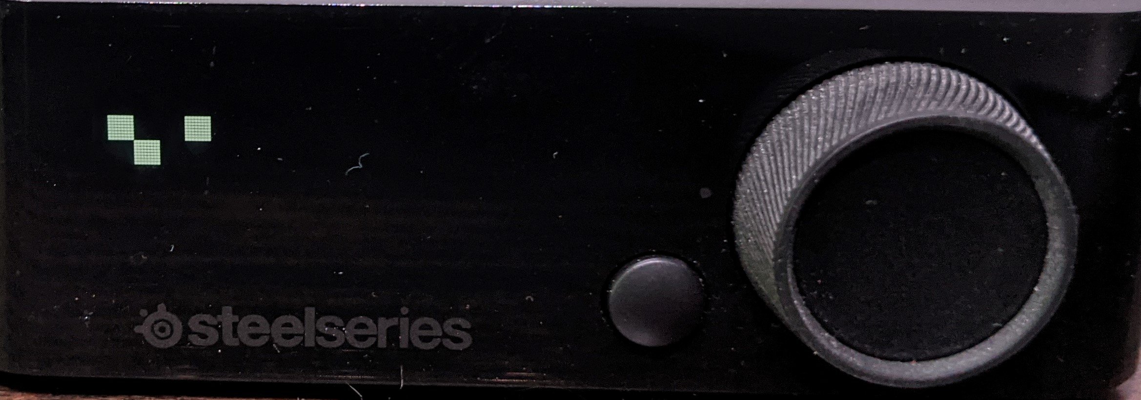
I'm including a copy of the structure of a packet below, along with a Wireshark capture of a few more. There are three writes included in the wireshark logs: an all-black screen, followed by an all-white screen, and finally the screen with the pattern in the picture below, which will hopefully make sense in a minute.
Looking at the USB packets, it seems like the payload for writing to the screen always begins with d200. That's then followed by 768 bytes of image data (screen is 128x48, so 6144 monochrome pixels -> 768 bytes). The packet is zero-padded out to 1024 bytes.
The data isn't a pixel-by-pixel raster, however. It seems like it's divided up into tiles of 8x8 pixels, each of which is described by an 8-byte block. Each byte of the block represents a column of pixels in the tile - byte 1 -> left column, byte 2 -> second column, ..., byte 8 -> right column.
The tiles themselves are rasterized left->right then top->bottom, 16 tiles wide and 6 tall. The pattern in the picture is three white tiles in the picture: white tile, 2 black tiles, white tile, 12 black tiles, (new line) black tile, white tile, then black for the rest, which looks like this:
ffffffffffffffff00000000000000000000000000000000ffffffffffffffff000000000000000000000000000000000000000000000000000000000000000000000000000000000000000000000000000000000000000000000000000000000000000000000000000000000000000000000000000000000000000000000000
0000000000000000ffffffffffffffff0000000000000000...
Hopefully this makes some amount of sense; I get the feeling I'm lacking the terminology to properly describe what I'm talking about. Let me know if I can clarify or investigate anything further.
Thanks!
Sam
Frame 2: 1060 bytes on wire (8480 bits), 1060 bytes captured (8480 bits) on interface wireshark_extcap3124, id 0
USB URB
[Source: host]
[Destination: 1.12.0]
USBPcap pseudoheader length: 28
IRP ID: 0xffffe60a9aa8b010
IRP USBD_STATUS: USBD_STATUS_SUCCESS (0x00000000)
URB Function: URB_FUNCTION_CLASS_INTERFACE (0x001b)
IRP information: 0x00, Direction: FDO -> PDO
0000 000. = Reserved: 0x00
.... ...0 = Direction: FDO -> PDO (0x0)
URB bus id: 1
Device address: 12
Endpoint: 0x00, Direction: OUT
0... .... = Direction: OUT (0)
.... 0000 = Endpoint number: 0
URB transfer type: URB_CONTROL (0x02)
Packet Data Length: 1032
Control transfer stage: Setup (0)
[bInterfaceClass: Unknown (0xffff)]
Setup Data
bmRequestType: 0x21
0... .... = Direction: Host-to-device
.01. .... = Type: Class (0x1)
...0 0001 = Recipient: Interface (0x01)
bRequest: 9
wValue: 0x0300
wIndex: 0 (0x0000)
wLength: 1024
Data Fragment: d200ffffffffffffffffffffffffffffffffffffffffffffffffffffffffffffffffffff…
The raw hex for the packet that wrote the pattern in the picture is here:
1c001040e9aa0ae6ffff000000001b000001000c00000208040000002109000300000004d200ffffffffffffffff00000000000000000000000000000000ffffffffffffffff0000000000000000000000000000000000000000000000000000000000000000000000000000000000000000000000000000000000000000000000000000000000000000000000000000000000000000000000000000000000000000000000000000000000000000ffffffffffffffff0000000000000000000000000000000000000000000000000000000000000000000000000000000000000000000000000000000000000000000000000000000000000000000000000000000000000000000000000000000000000000000000000000000000000000000000000000000000000000000000000000000000000000000000000000000000000000000000000000000000000000000000000000000000000000000000000000000000000000000000000000000000000000000000000000000000000000000000000000000000000000000000000000000000000000000000000000000000000000000000000000000000000000000000000000000000000000000000000000000000000000000000000000000000000000000000000000000000000000000000000000000000000000000000000000000000000000000000000000000000000000000000000000000000000000000000000000000000000000000000000000000000000000000000000000000000000000000000000000000000000000000000000000000000000000000000000000000000000000000000000000000000000000000000000000000000000000000000000000000000000000000000000000000000000000000000000000000000000000000000000000000000000000000000000000000000000000000000000000000000000000000000000000000000000000000000000000000000000000000000000000000000000000000000000000000000000000000000000000000000000000000000000000000000000000000000000000000000000000000000000000000000000000000000000000000000000000000000000000000000000000000000000000000000000000000000000000000000000000000000000000000000000000000000000000000000000000000000000000000000000000000000000000000000000000000000000000000000000000000000000000000000000000000000000000000000000000000000000000000000000000000000000000000000000000000000000000000000000000000000000000000000000000000000000000000000000000000000000000000000000000000000000000000000000000000000000000000000000000000000000000000000000000000000000000000000000000000000000000000000000000000000000000
Which produces:
Arctis Pro Wireless OLED only.pcapng


")