

Mask Blue
-
Posts
11 -
Joined
-
Last visited
Mask Blue's Achievements
")


-
Thank you very much for your help, but I added these values and it didn't work correctly. For example, the button doesn't move as the volts and watts sensor changes. In the values you sent, shouldn't there be a point after the decimal place?
-
Thank you very much for your help, my friend. So, I want to use the value from 0 to 200 for watts.
-
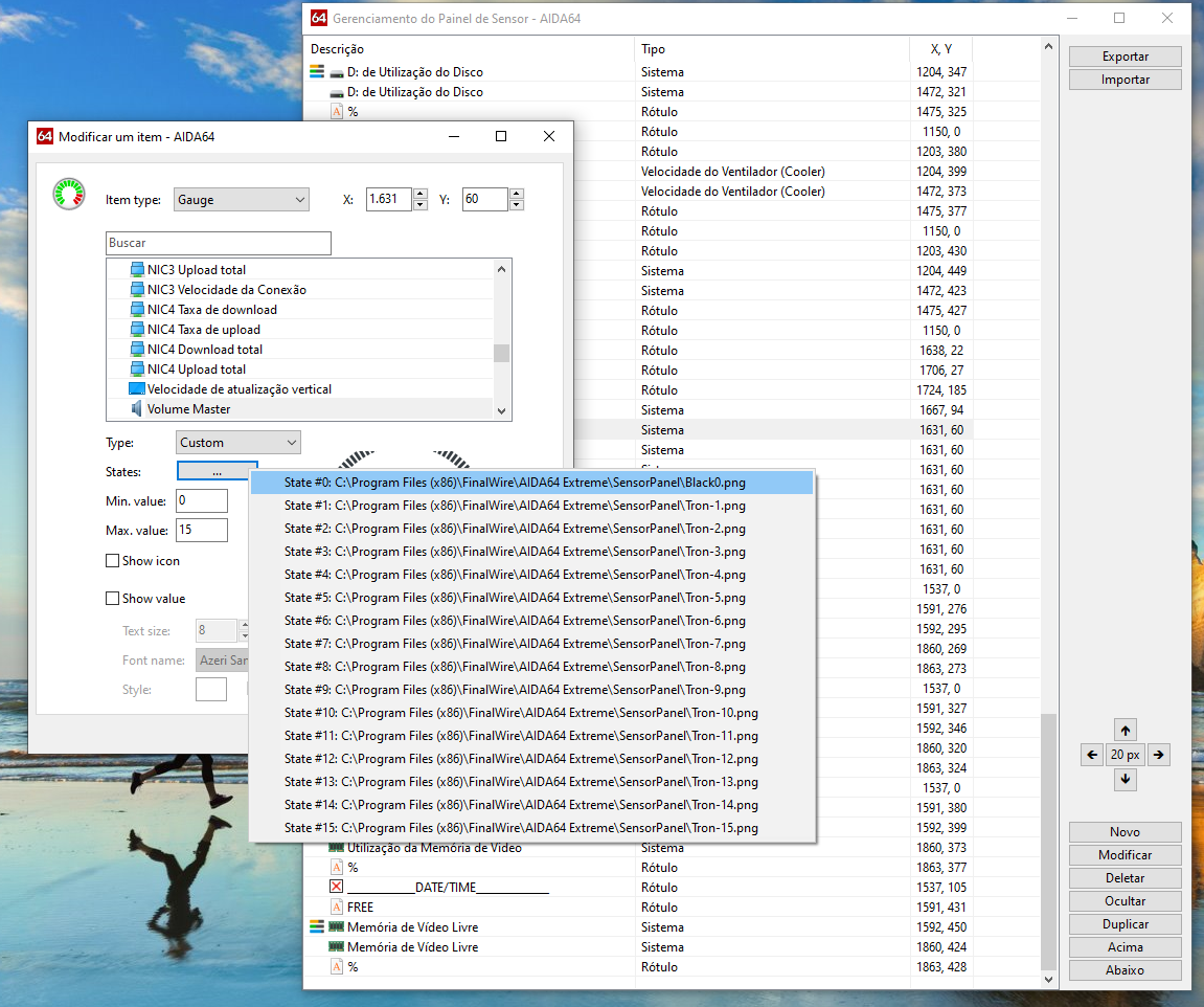
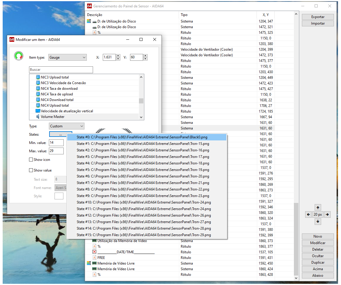
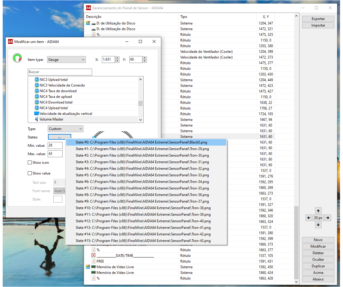
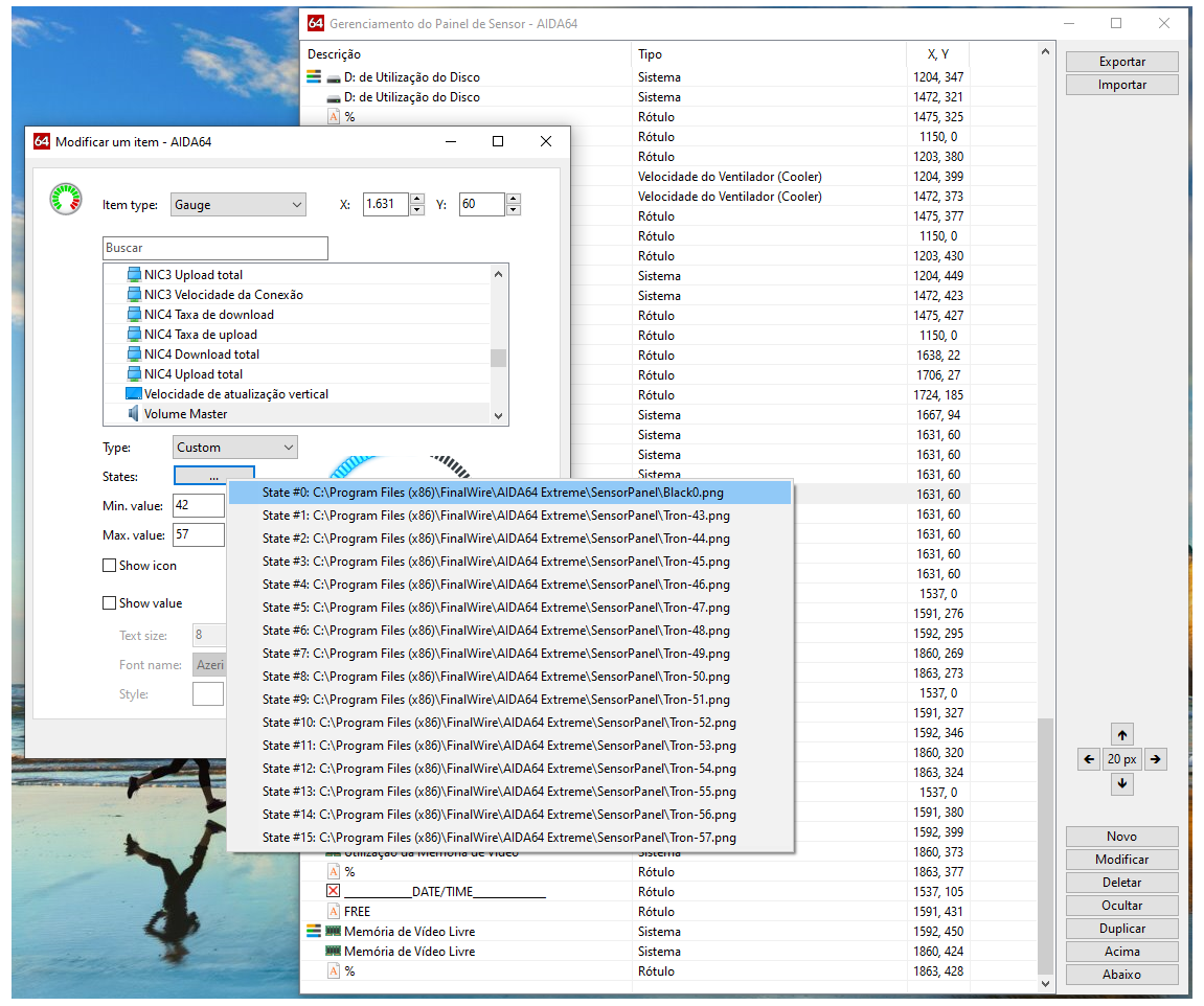
I created a button with 100 states and would like to assign the VOLTS and WATTS sensors to this button, but I don't know which values to assign in the minimum value and maximum value fields. I tried some combinations, but without success. Is it possible to assign these values? If anyone can help, I would be very grateful.
-
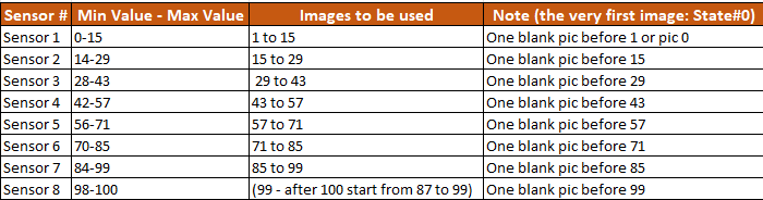
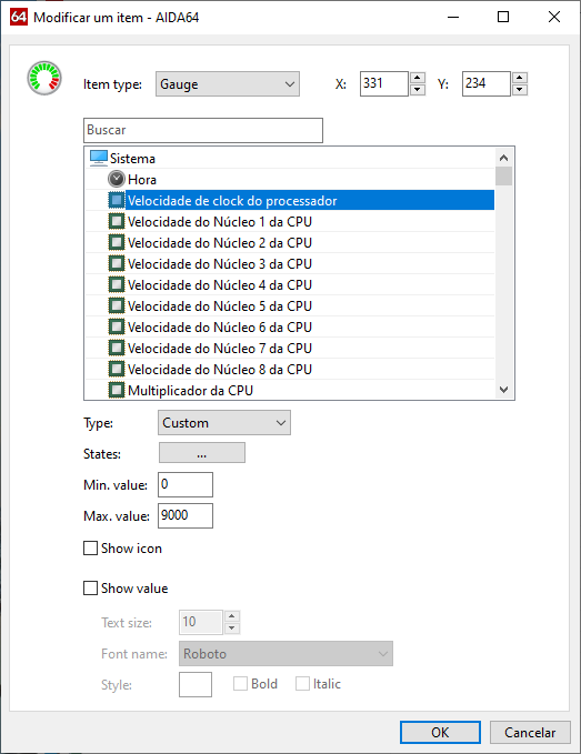
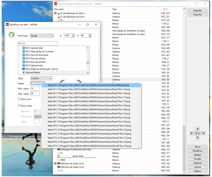
I appreciate your help, but I'm not complicating anything, I just wish you understood what I'm trying to explain. If we use this table to create a sensor to measure the processor clock, this table won't function correctly. I've even used the same table and followed all the steps to create a clock sensor, but it doesn't work properly. I just want to know what minimum and maximum values I should use in the sensor for it to work correctly, considering that the maximum and minimum values of the CPU are from 0 to 9000
-
My question makes complete sense: all processors have minimum and maximum values ranging from 0 to 9000. Therefore, if we follow this table, the sensor will not work correctly. That's why I asked if having maximum values of 9000, the codes will not work.
-
This answer your question? CPU Intel I7-10700K
-
@Shepherd Thank you very much for your help. However, I'm having an issue. I'm trying to create a new sensor for the CPU clock, and I used the same information you suggested, but it's not working. What would be the maximum and minimum values I should use in each state, considering that the maximum CPU clock value is 9000?
-
I would like to express my gratitude to @Surjeet and @Shephard for helping with this sensor. I would never have figured this out on my own without your valuable assistance. You guys were amazing. Once again, thank you very much.
-
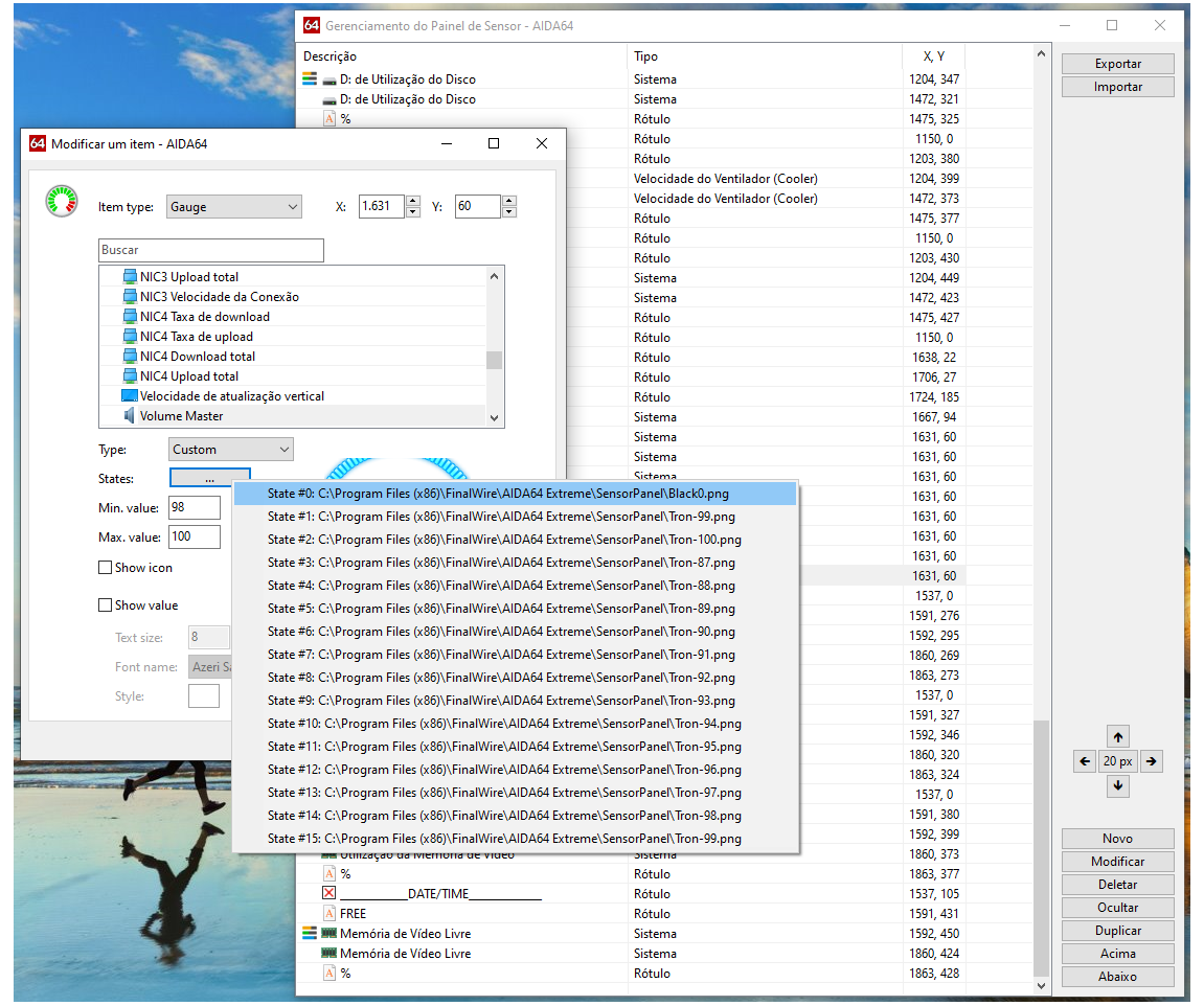
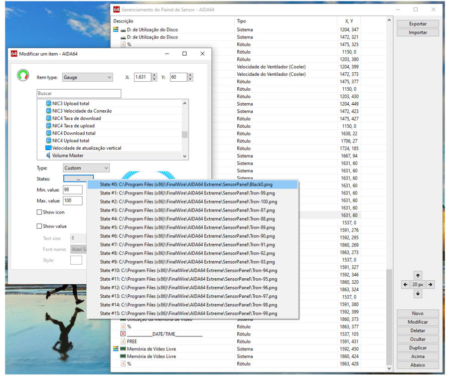
I would like to express my sincere gratitude for your valuable assistance and for being so kind in responding so clearly. I followed your instructions, as can be seen in the screenshots. The sensor I shared is for volume control. It works well until it reaches 80% of the volume, but when increasing it from 80% to 100%, although the volume reaches 100%, the sensor doesn't completely fill the space, as shown in the image. I'm not sure if there is anything missing or if additional settings are needed. I added a transparent background to each sensor, identified with the name "Black0.


-
From what I understood, so if I create a sensor with 100 steps, it won't work correctly? Is that it? When we use sensors with 16 steps, they don't accurately track the temperature in the case of the CPU or any other sensor. I apologize for my ignorance. Could you please take a screenshot of how I would set the maximum and minimum values? I would like to understand more about this, with sensors of 32 and 64, and if possible, with 100 steps to make them work correctly.
-
Hello, I'm new to the community, and I have some knowledge in Photoshop (PS) and Illustrator (AI). I'm creating some custom sensors, and I searched the forum for information on how 100-time sensors work, but I couldn't find anything. I'm confused about how to use, for example, the minimum and maximum values. What values should I input there, for instance, if I've created a gauge to control volume? Could you please provide some assistance on how to do this?