

Shephard
-
Posts
81 -
Joined
-
Last visited
-
Days Won
1
Content Type
Profiles
Forums
Events
Everything posted by Shephard
-
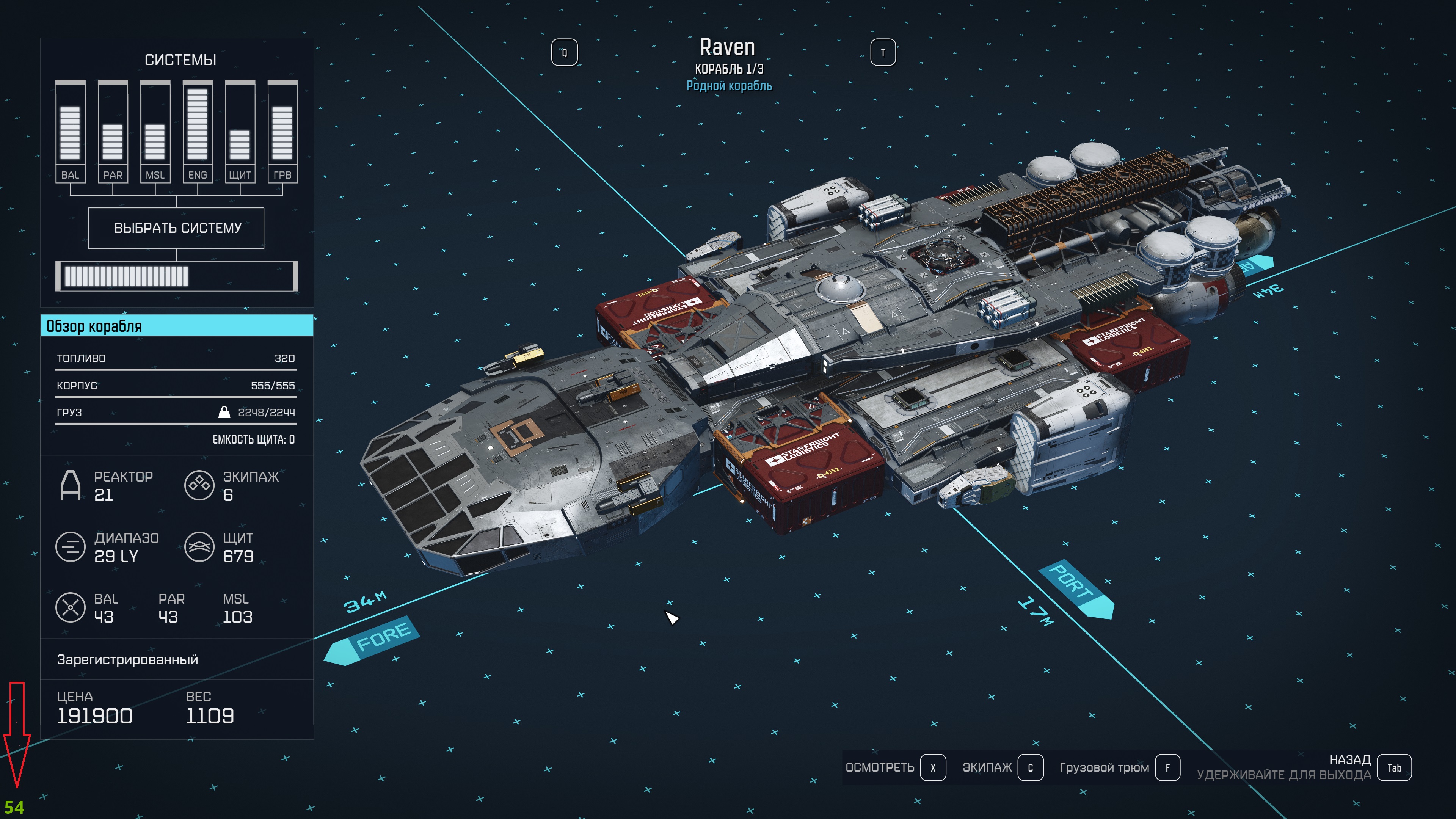
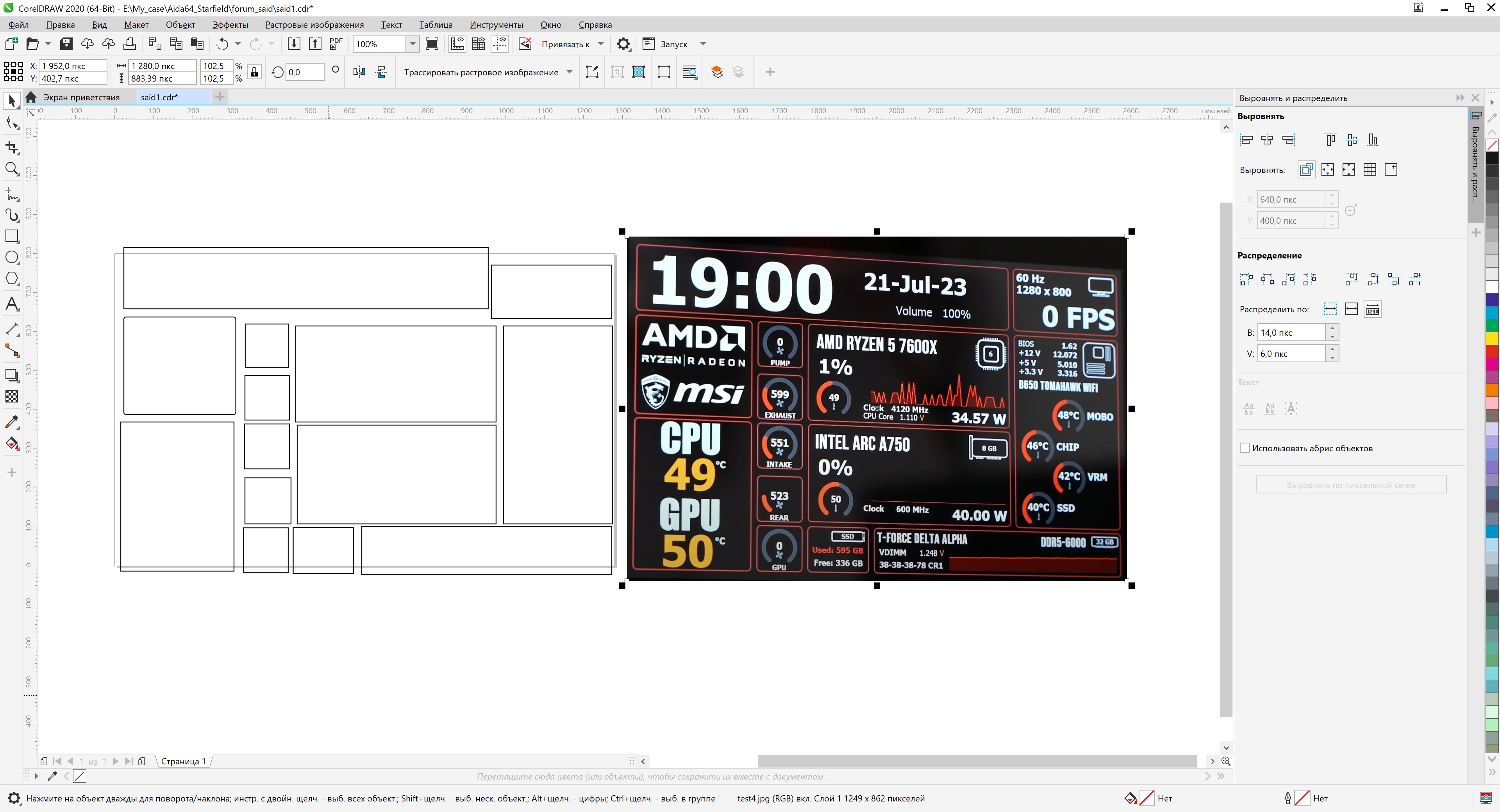
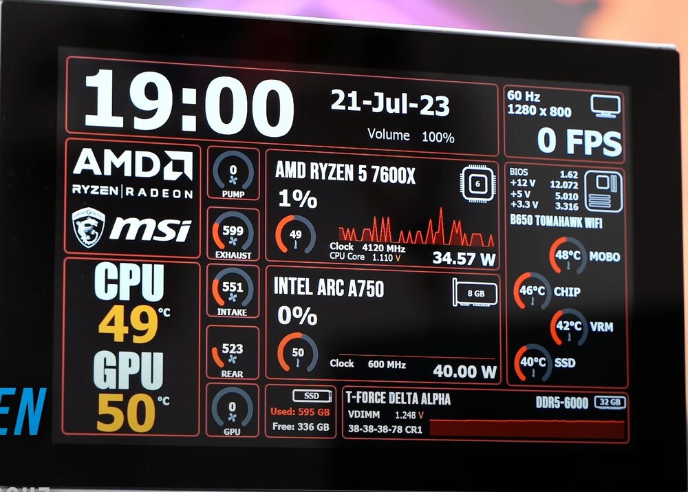
and this is what it looks like, but I thought there were also sensors on the side... well, great, that means less problems for the person

-
then it may already look like something, with your permission, I would like to rest today, we will continue tomorrow, I hope you have time to get the result

-
I don’t know all the sensors in this project, and even more so the sensors you want to use, it would be nice to decide the background is a little more complicated, it looks like the color is not uniform blue, I think it will be possible to add the background later, as a separate picture
-
At the edges it looks like you can adjust the volume level..

-
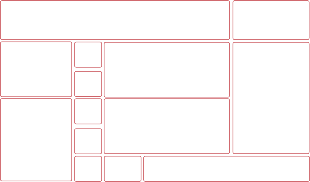
So, the foundation for our common project has been laid, what background would you like to use?

-
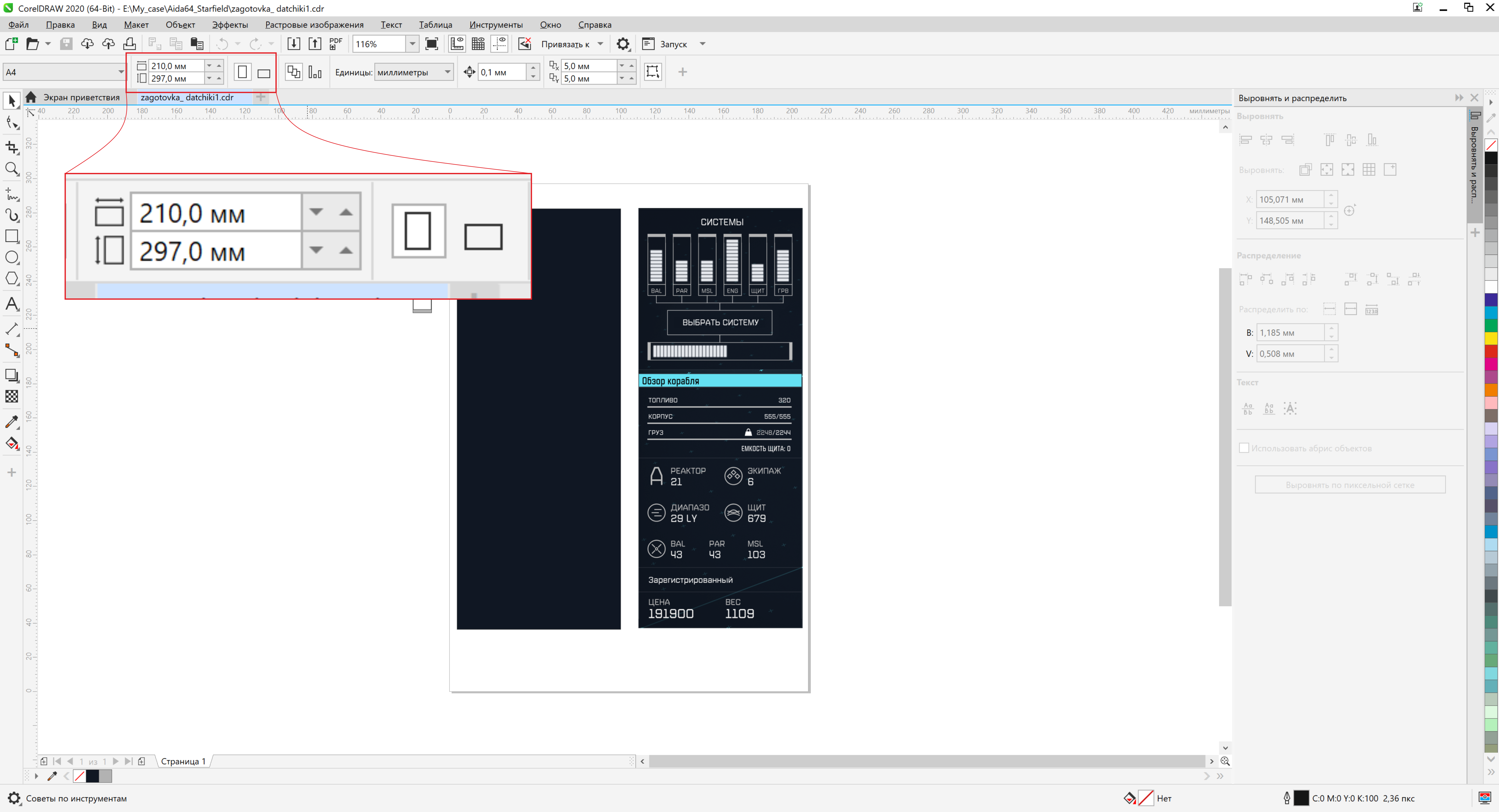
what size do you need, we don’t have to wait for the owner, but draw it together with you
-
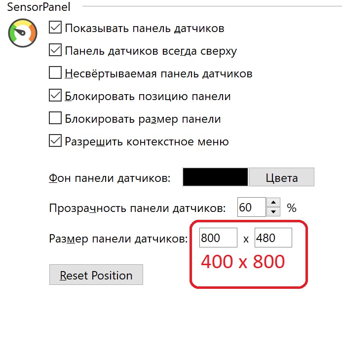
just swap your resolution
-
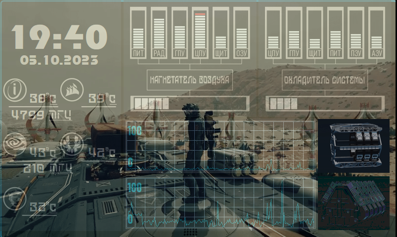
While I'm working on the compass, I decided to change the background a little, it doesn't seem bad 753049039_2023-10-0519-30-25.mkv
-
I'm glad it was useful to someone
-
It’s not clear what the problem is, scale it, this can be done in any editor, well, there may be a loss of time to fix the sensors, although I don’t see any problem here if you have the sources
-
as far as I know, RTSS has an error setting, you need to study this, secondly, if it is important for you to simply see frames on the screen, then you can enable the counter in the video card driver; it will display frames directly on the main screen, or perhaps your display simply does not have time to update the data on the screen..

-
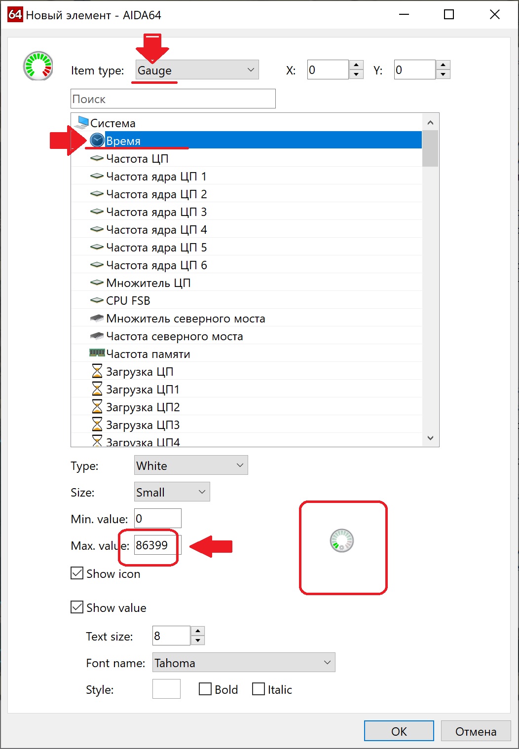
when you install a measure sensor, there is one incomprehensible time sensor, I still don’t understand why it has these settings by default and what it does.. can someone explain

-
Is it so important for you that it shows exactly 60 or 30? draw a number. most likely the answer is on the surface, somewhere there is a delay in the time the counter is displayed on the screen, you need to understand what vertical synchronization is, this is when the monitor frequency and the game frame rate are synchronized to display a smooth image without tearing, on modern monitors and TVs (in fact there is almost no difference), the refresh rate of the matrix can be different, 60Hz, 75Hz, 144Hz and so on, at a frequency of 60Hz, 1 frame changes in a time of 16.67ms and here it is important to understand that without triple buffering an error is possible, that is, a situation occurs when the frame was either not prepared, or was not processed by the video card, or was stuck in the queue at the monitor.. something like this The same thing happens with the LCD display of your RTSS.
-
I'll be making a new panel for the starfield, I'd like to add a compass while I'm putting together the compass animation
-
It’s a little strange to me why you are not satisfied with the use of transparency, I use three tools at once for one monitor, this is a program for live wallpaper, RSLCD, Sensor Panel (40% transparency). On modern computers, especially if you have a sensor tracking monitor installed for something, not many resources will be used
-
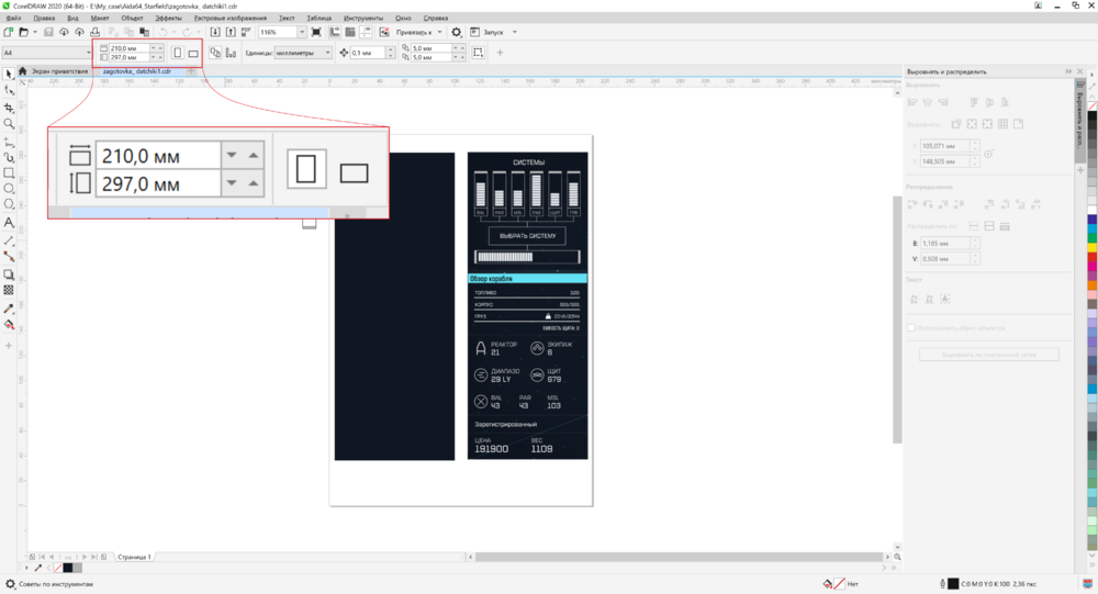
I can try to make a design if you draw it by hand on paper and send me a photo, please indicate only approximate dimensions
-
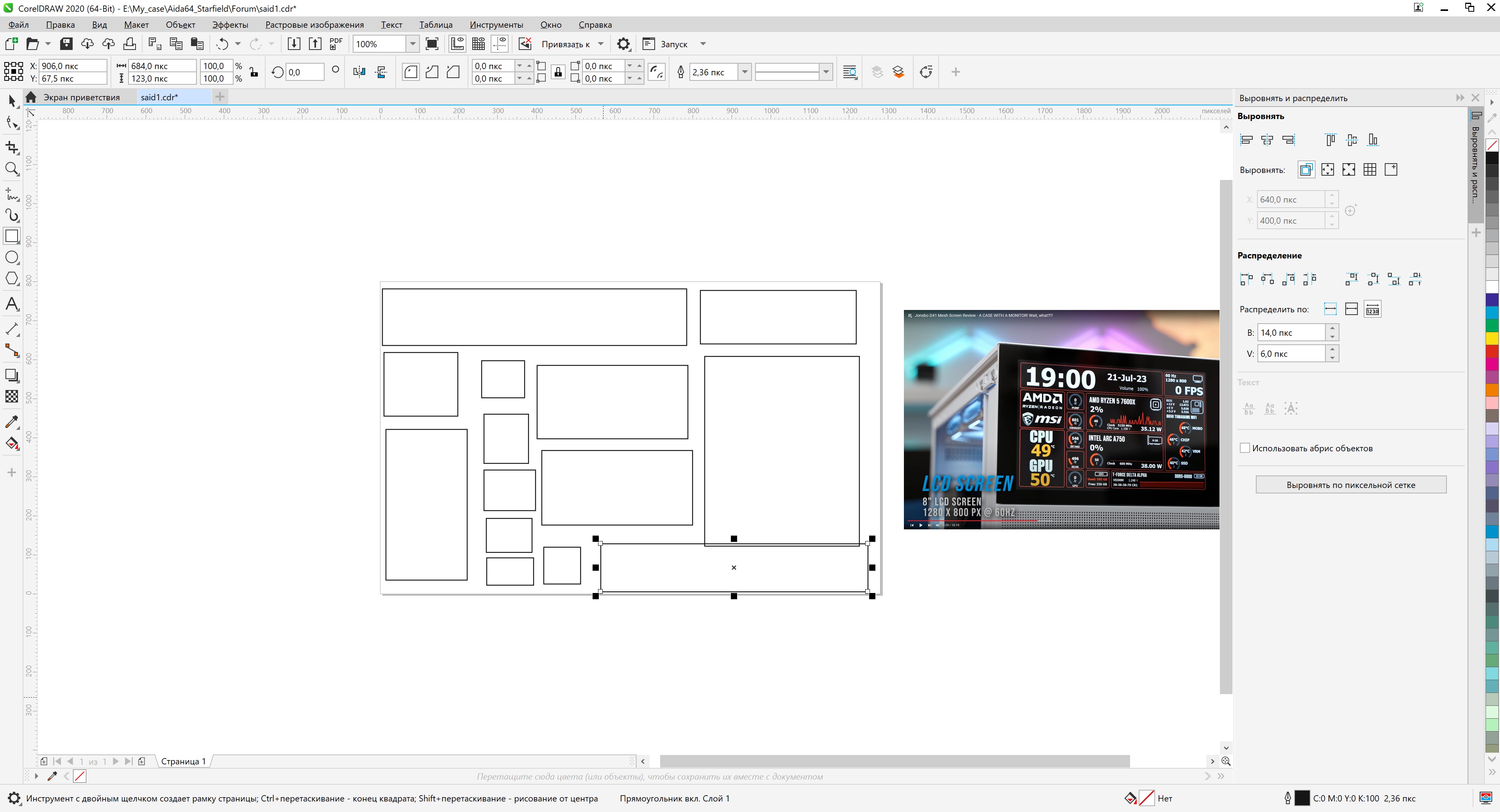
I gave the sources, scale to any size, the png file is easily converted
-
install sensors
-
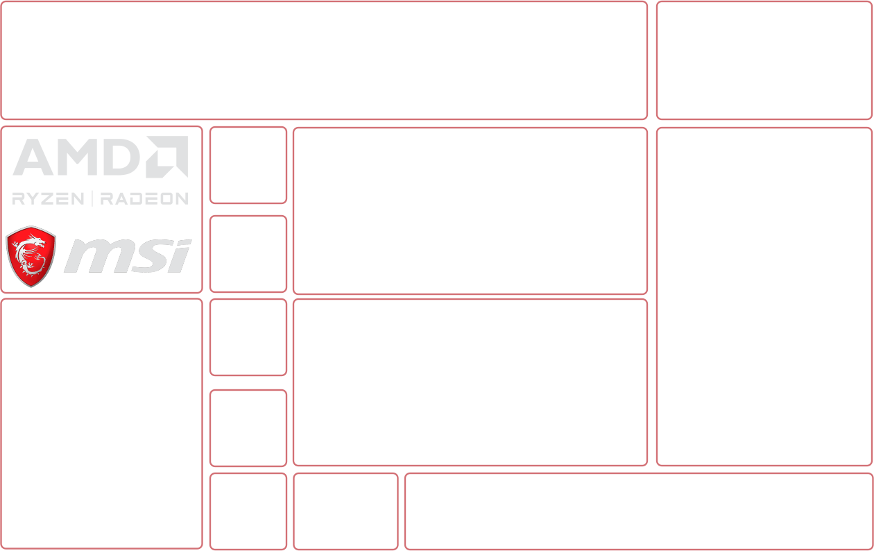
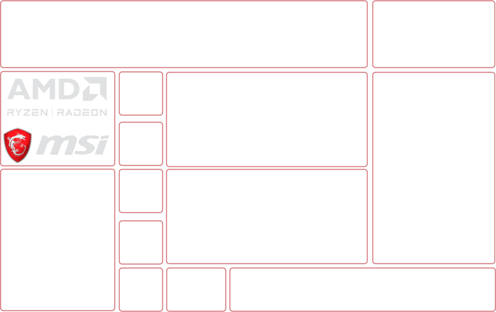
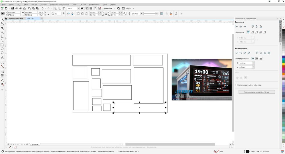
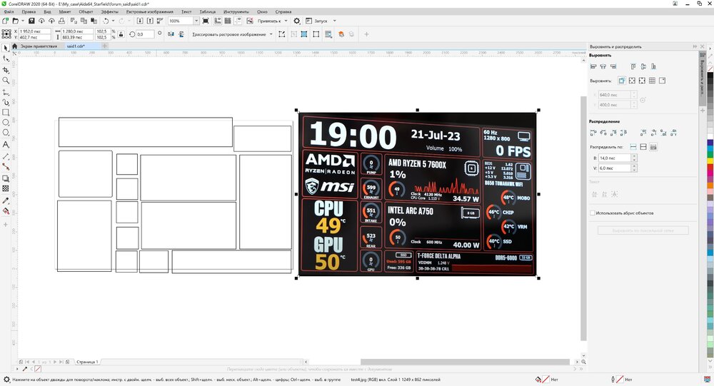
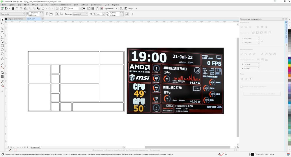
Well, what if someone wants to use it, so I spent 15 minutes preparing 1280 x 800 archived sources forum_said.7z
-
The panel is very simple, just squares and inscriptions, the most complex element is the round design of the sensor, it is not clear how many divisions it is made of..
-
I approached the question responsibly, when I also had to study such moments
-
you have an error in one of the sensors worth 84-89 but you need 84-99
-
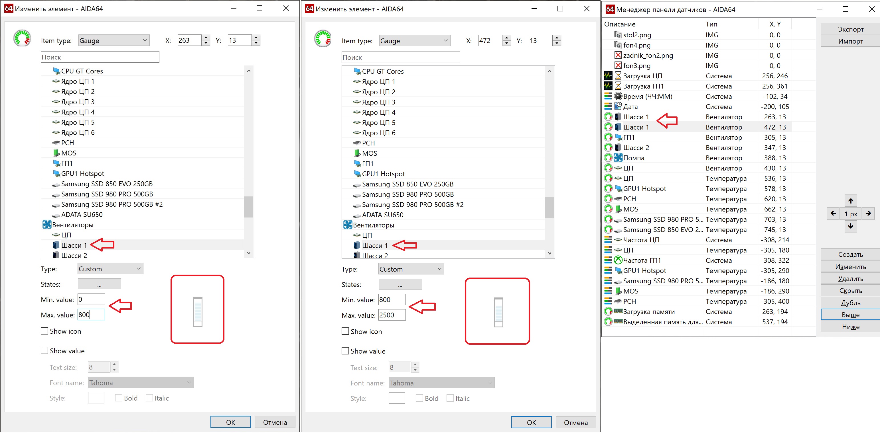
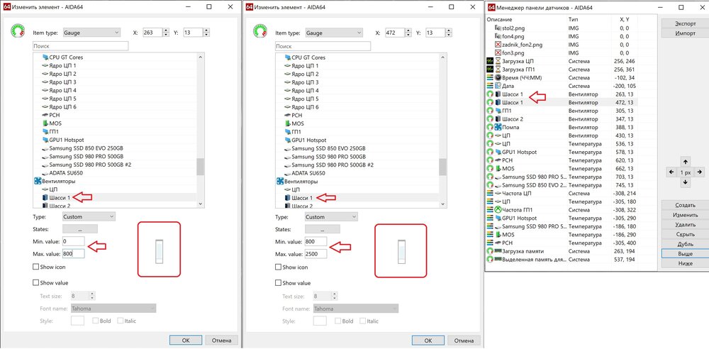
I have a program in Russian, but I think it will still be clear to you from the picture, you need to install as many of the same sensor as you have levels of 16 each, that is, if you have 32 levels, then you need to install 2 identical sensors, but on one set minimum 0 maximum 16 on the second set minimum 16 maximum 32, look at the photo of how I made a 2500 rpm fan, the same fan is duplicated twice, but installed in different places, one lower, the second higher, the one below from 0 revolutions to 800 (this is 0-16), and the second 800 revolutions to 2500 revolutions (this is 0-16) don't hesitate to ask how I can help
-
if you want to create a level not of 16 steps, but for example 32, then you need to create 32 pictures, install two sensors of the same type, set the limit in the first sensor to minimum 0 maximum 16, on the second sensor set minimum 16 to maximum 32, and so on up to 100 , but it’s clear that you won’t be able to make exactly 100; if you divide 100 by 16, you get 6.25 sensors, this doesn’t happen, otherwise there will be gaps in the pictures, which means you either need to put 6 sensors and sacrifice some levels, or put 7 sensors and stretch some levels .. however, in practice I will say that this is not required, a level of 2 pixels with a gap of 2 pixels per 100 levels will occupy 400 pixels, this is just a huge column or circle (depending on the design), if you need to measure temperature, I advise you to set the minimum 20 degrees maximum 80 degrees Celsius, it is unlikely that your cooling will work in more extreme conditions..