rinaldop
Members-
Posts
636 -
Joined
-
Last visited
-
Days Won
24
Content Type
Profiles
Forums
Events
Everything posted by rinaldop
-
I see that the panel has a remote to control the RGB lighting it is a shame that they did not include a way to control the panel brightness. I have heard of some people finding brightness controls buried under the case enclosure. My only suggestion is to contact the manufacturer and ask them. Just for fun I decided to look if there was a way to control the brightness of a secondary screen and found this. https://www.thewindowsclub.com/how-to-control-brightness-of-multiple-monitors-on-windows Enjoy!
-
Aida64 has nothing to do with the brightness of your panel. You need to find the manual for it. Many panels change brightness by pushing a button on the back. What panel do you have?
-
Unfortunately only the moderators can do that and interestingly someone asked for that before but it did not happen.
-
I have been saying that for months, but since you already use 100% scaling I did not think you needed it. Glad you got it working! https://forums.aida64.com/topic/12641-scaling-issues-windows-10-msi-z790-carbon/#comment-55350
-
Did you even try to search? Look here https://forums.aida64.com/search/?q="1024x600"&quick=1&type=forums_topic&item=667
-
This is a strange one. I know that the creator of the panel said it was 1024x600 but the panel data says it is 480X819 <SPWIDTH>480.00</SPWIDTH><SPHEIGHT>819.20</SPHEIGHT> Try this one that I know is 1024x600 because I made it! Let's see what happens. https://forums.aida64.com/topic/667-share-your-sensorpanel/page/463/#comment-56067
-
Two things usually cause that 1. You do not have the proper font installed 2. You do not have Windows scaling set to 100%
-
Sure, it might work better if you switch it to monitor a single CPU core or maybe clock speed - whatever changes the fastest on your system. Also what does "storno" mean?
-
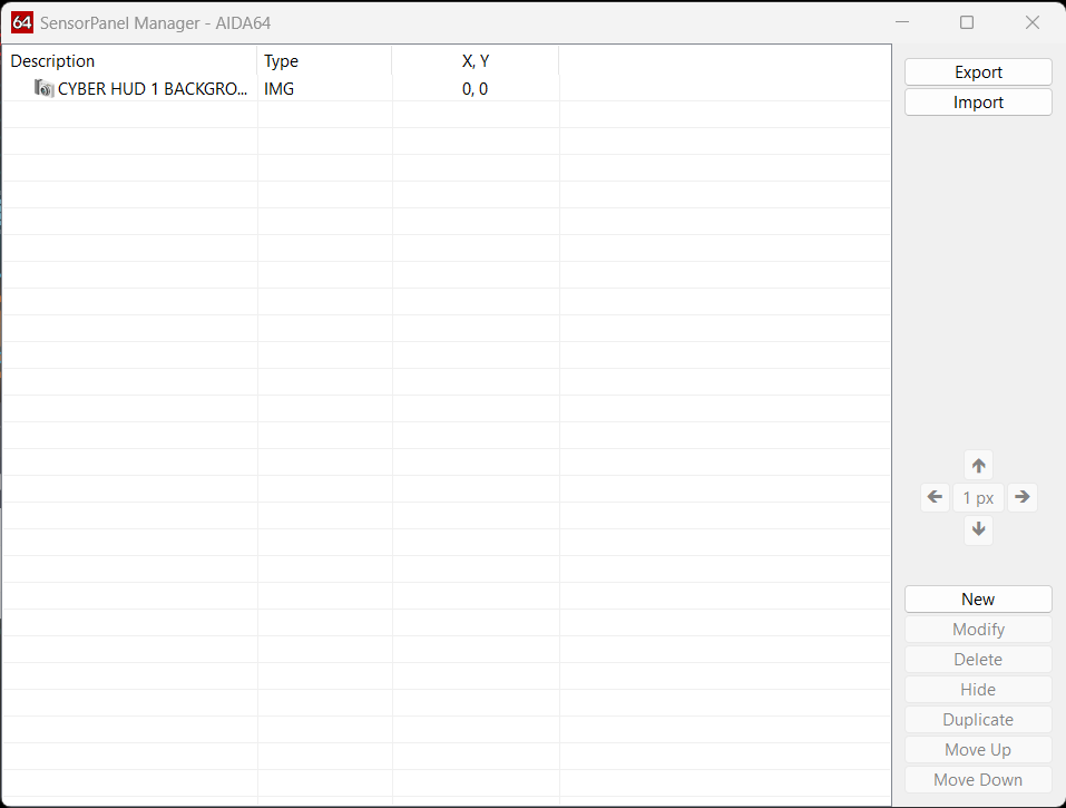
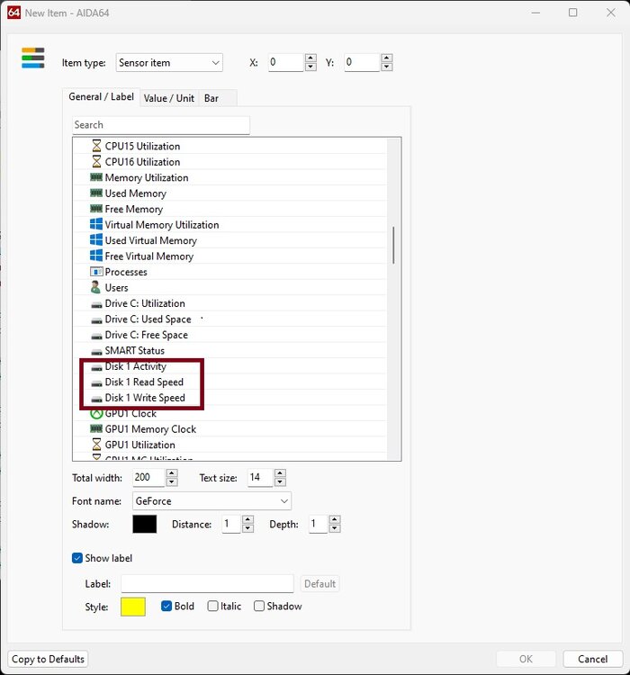
Load an existing panel right click on it and select sensorpanel manager select all entries and delete them click "new" and for item type select image click on the ... for image file and select your image It must be the first item on the list and will look like this
-
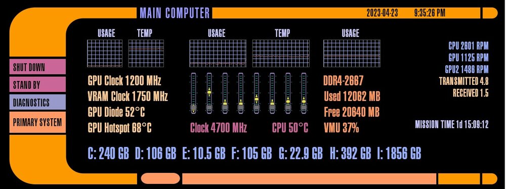
Yes, the background is just a .png or .jpg that can come from anywhere or be created just for the panel. The background can also be blank. Then you add the sensors on top of that. Thanks for the compliment! I am glad you like my other panel!
-
Watch this video and if you have more questions just ask
-
I did it. Here is what I did, when I saved all of your images I had 60. I created 8 gauges and set them to monitor CPU utilization. With 8 gauges there is enough for an image to be displayed for every 1% change in CPU utilization from 0-100%. The images go up from 0-60 as CPU utilization increases and then go backwards from 60-20 as CPU utilization continues to increase from 61-100. . Unfortunately there is no way to share a completed gauge so I am uploading a sensorpanel with the gauges. If you want to use this in a panel I suggest that you start with this and add the rest of your items to it. Unfortunately CPU utilization does not change very fast so the animation of the gauge does not move much. Take a look and see what you think. Maybe we can make some changes to make it more interesting. 100frames-2024-01-08.sensorpanel
-
I created one Star Trek panel before https://forums.aida64.com/topic/667-share-your-sensorpanel/page/454/#comment-55383 I was thinking of creating another one using this look. Is there any interest?
-
OK, I will do it for you and post it here.
-
-
.gif files are not supported in sensorpanel only in RemoteSensor and those must be viewed in a browser.
-
Here it is https://forums.aida64.com/topic/667-share-your-sensorpanel/page/326/#comment-47283
-
Here it is https://forums.aida64.com/topic/667-share-your-sensorpanel/page/239/#comment-42253
-
It looks like the fonts are VALCOL, VALBI, Advanced Pixel LCD-7
-
That guy has not logged on since December 28, 2022.
-
Hm, you need to explain what you mean by that;)
-
fixed: Exporting RemoteSensor LCD items no longer saves Hidden items
rinaldop replied to KC8DKT's topic in Bug reports
Now that I re read your message I have had this happen to me once or twice, but I don't remember if the items that I lost were hidden. I never figured out why it happened but it has not happened again. Try creating them from inside the sensor panel manager instead of right clicking on the panel and clicking new.


